FAG Spherical Bearings on Adapter Sleeves Wholesale Supplier
- Published
- Installation & Maintenance
- By author

FAG Spherical Bearings on Adapter Sleeves Wholesale Supplier
Tighter is not better. Over-tightening the lock nut eliminates the thermal expansion clearance required for high-load operations, leading directly to bearing burnout rather than extended service life.
The correct mounting of FAG spherical bearings on adapter sleeves depends entirely on two factors: precise control of lock nut tightening torque and accurate measurement of residual radial internal clearance. Failure to adjust these parameters results in inner ring slippage on the shaft or excessive preload, both of which cause premature failure regardless of bearing quality.
I still remember the dust choking the air at a quarry site outside Riyadh. The crusher had been running for less than two months when it seized. The local maintenance team blamed the bearing quality, pointing at the scorched outer ring. But when I pulled the assembly apart, the issue was not material fatigue. The lock nut on the adapter sleeve had not been driven far enough up the taper. The inner ring was loose, spinning slowly against the shaft surface while the rollers screamed under load. The radial clearance had vanished not because of wear, but because the initial installation never achieved the proper seating position. This is a common scene in heavy industry. Many operators assume that installing a spherical roller bearing on an adapter sleeve is a simple mechanical task. In reality, it is a precision procedure where millimeters of axial displacement translate into critical changes in internal geometry. [NEED_CITE: standard procedure for mounting spherical roller bearings on tapered seats]
Understanding why these failures happen requires looking beyond the brand name. As a global source for industrial components, we see the same pattern repeat across different regions and industries. The bearing itself is often genuine and robust. The failure lies in the interface between the bearing, the adapter sleeve, and the shaft. This guide details the technical steps required to ensure longevity, focusing on the mechanics that most installation manuals gloss over.
Why Do Bearings Fail on Adapter Sleeves?
The primary cause of premature failure in these assemblies is not external contamination or lubrication issues, but incorrect internal clearance management. When a spherical roller bearing is mounted on a cylindrical shaft using an adapter sleeve, the sleeve acts as a wedge. As the lock nut tightens, it drives the sleeve further into the bearing bore. This action expands the inner ring diameter, reducing the radial internal clearance.
If the nut is not tightened sufficiently, the inner ring does not grip the shaft with enough friction. Under heavy vibrational loads, such as those in a vibrating screen or crusher, the inner ring can creep or slip relative to the shaft. This micro-movement generates heat through friction, leading to fretting corrosion and eventual seizure. Conversely, if the nut is over-tightened, the radial clearance is reduced to zero or becomes negative. The rolling elements are then preloaded excessively. During operation, thermal expansion of the inner ring further reduces any remaining clearance, causing the rollers to bind. This generates extreme heat, rapidly degrading the lubricant and leading to catastrophic failure. [NEED_CITE: relationship between radial clearance reduction and bearing temperature rise]
Most technicians rely on the “feel” of the wrench or a predefined number of turns. This approach is flawed because it ignores variations in shaft tolerance, sleeve fit, and bearing manufacturing tolerances. The only reliable method is to measure the actual reduction in radial clearance during installation. This ensures that the bearing retains enough space for thermal expansion while maintaining a secure grip on the shaft. For distributors and MRO operators, understanding this mechanism is crucial for troubleshooting recurring failures in client equipment. It shifts the focus from blaming product quality to verifying installation practice.
Step 1: Preparation and Shaft Inspection
Before touching the bearing, the foundation must be verified. The shaft and adapter sleeve must meet specific dimensional and surface quality requirements. A damaged shaft surface or an incorrect tolerance class will prevent the adapter sleeve from seating properly, regardless of how carefully the lock nut is tightened.
Inspect the shaft for scratches, burrs, or corrosion. Any imperfection on the shaft seat can act as a stress concentrator or prevent the sleeve from sliding smoothly onto the taper. Clean the shaft thoroughly with a non-residue solvent. Apply a thin layer of light oil to the shaft surface to facilitate the sliding of the adapter sleeve. Do not use grease at this stage, as it can trap debris and interfere with the seating process.
Check the adapter sleeve for damage. Ensure the split in the sleeve is clean and free of deformation. The sleeve should slide onto the shaft with moderate resistance. If it slides on too easily, the shaft diameter may be undersized. If it requires excessive force, the shaft may be oversized or dirty. Verify the shaft diameter against the bearing manufacturer’s specifications. [NEED_CITE: ISO tolerance classes for shaft fits with adapter sleeves]
For wholesale suppliers and distributors, providing clients with clear guidelines on shaft preparation can reduce return rates due to installation errors. Many end-users overlook this step, assuming the new parts will compensate for poor shaft conditions. Emphasizing the importance of surface integrity helps set realistic expectations for performance.
Step 2: Mounting and Lock Nut Tightening
Mounting the bearing onto the adapter sleeve requires careful alignment. Slide the bearing onto the sleeve, ensuring it is seated correctly against the shoulder of the sleeve. Hand-tighten the lock nut to hold the bearing in place. Do not use tools at this stage. The goal is to position the bearing without inducing any preload.
The critical phase begins when you start to tighten the lock nut. Use a hook spanner or a pin wrench designed for the specific lock nut size. Avoid using impact wrenches or hammers, as these can damage the bearing raceways or distort the sleeve. Tighten the nut gradually while rotating the bearing to ensure the rollers settle into their correct positions. This prevents false readings of resistance due to misaligned rolling elements.
As you tighten, monitor the axial movement of the inner ring. The nut drives the sleeve up the taper, expanding the inner ring. This process must be controlled. Do not rely solely on the torque applied to the nut, as friction variables can make torque an unreliable indicator of clamp force. Instead, prepare to measure the radial clearance continuously. [NEED_CITE: recommended tools for tightening lock nuts on adapter sleeves]
In our experience supporting clients across multiple regions, we observe that many failures stem from rushing this step. Operators often tighten the nut quickly to save time, missing the subtle signs of proper seating. Patience here pays off in extended service life. For large-scale projects, such as conveyor pulley replacements in mining operations, taking the extra time to verify each step prevents costly downtime later.
Step 3: Radial Clearance Adjustment
This is the most critical step in the entire process. The goal is to achieve a specific residual radial internal clearance after mounting. This value is determined by the bearing size and operating conditions. The manufacturer provides a table specifying the allowable reduction in radial clearance for each bearing size.
Measure the initial radial clearance before mounting if possible, or refer to the manufacturer’s catalog for the nominal unmounted clearance. During tightening, periodically stop and measure the current radial clearance using feeler gauges. Insert the gauge between the topmost roller and the outer ring raceway. Rotate the bearing slightly to ensure the roller is in the correct position for measurement.
Continue tightening the lock nut in small increments, checking the clearance after each adjustment. Stop when the measured clearance matches the target residual value specified for that bearing size. Do not go below this value. Over-reduction leads to preload and overheating. Under-reduction leads to slippage and fretting.
Our technical support team often assists distributors with cross-brand clearance calculation sheets. Since different brands may have slight variations in tolerance classes, having access to precise data ensures that the installation meets the specific requirements of the bearing in hand. We supply genuine FAG and INA lock nuts and accessories to ensure compatibility and reliability in this critical adjustment phase. [NEED_CITE: method for measuring radial internal clearance of spherical roller bearings]
For MRO operators dealing with emergency replacements, having the correct feeler gauges and reference tables on hand is essential. Guessing the clearance is a recipe for repeat failure. This step transforms the installation from a mechanical assembly into a precision engineering task.
Step 4: Final Locking and Verification
Once the correct clearance is achieved, the lock nut must be secured to prevent loosening during operation. Vibrations in heavy machinery can quickly undo even a properly tightened nut. Use a lock washer with tabs that engage with slots in the lock nut. Bend one tab into a slot to lock the nut in place. If the slots do not align, loosen the nut slightly until they do, but do not tighten further as this will alter the clearance.
Some applications use locking plates or wire locking methods. Follow the manufacturer’s recommendation for the specific application. After securing the lock, rotate the bearing manually to ensure it moves freely without binding. Check for any unusual noise or resistance.
Verify the final axial position of the bearing. Ensure it is centered correctly on the shaft and aligned with the housing. Misalignment can cause edge loading on the rollers, leading to premature fatigue. [NEED_CITE: standards for locking mechanisms on adapter sleeve assemblies]
Final verification is often skipped in fast-paced maintenance environments. However, a quick manual check can catch errors before the machine is energized. For equipment dealers, including this verification step in their service protocols adds value and reduces warranty claims. It demonstrates a commitment to quality beyond just supplying the part.
Conclusion
Proper installation determines bearing life. The quality of the component is secondary to the precision of its mounting on the adapter sleeve. By focusing on radial clearance adjustment and controlled lock nut tightening, operators can prevent the majority of premature failures. This approach saves time, reduces maintenance costs, and ensures reliable operation in demanding industrial environments.
Send Your FAG Bearing List for a Written Quote
FAG Bearing Supplier quotes spherical, cylindrical, tapered and thrust roller bearings together with housings and sleeves, for urgent replacements or planned shutdown orders. Any technical change is proposed separately and needs your approval.
- 1
Send your list by form, WhatsApp or email, position by position.
- 2
We confirm identification: exact version, complete assembly, and any clearly marked alternative.
- 3
Receive a written quote with designation, quantity, price and currency, stock status, estimated lead time and validity.
- Email: info@fagome.com
- Address:

Related FAG Bearing Maintenance Articles
More notes on version identification, mounting accessories and shutdown planning for heavy equipment.
 01
Oct 3, 2026 · Installation & Maintenance · 7 min read
FAG Bearing Maintenance Checklist: Wholesale Supplier for Bulk MRO Orders
Master the FAG bearing m…
Read the full article 02
Oct 3, 2026 · Installation & Maintenance · 7 min read
FAG Housing Seals: Genuine Wholesale Supplier for Bulk Orders
Optimize Seal Choices fo…
Read the full article 03 Oct 3, 2026 · Installation & Maintenance · 8 min read
FAG Bearing Shaft & Housing Fits: Wholesale Supplier
Mastering FAG bearing sh…
Read the full articleFAG Roller Bearings and Accessories for Heavy Equipment
Selected FAG bearings for mills, crushers, conveyors and industrial drives. Housings and sleeves can be quoted with the bearing.
Scroll sideways to browse →
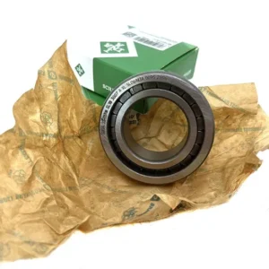
X&S INA Nup1007em Cylindrical Roller Bearing for Auto Motor Spare Part
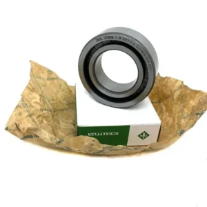
INA B7018C.T.P4S B7018E.T.P4S Angular Contact Ball Bearing for Turbojet
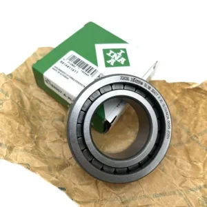
X&S NN3060/Y1 Double Row Cylindrical Roller Bearing for Heavy Load
X&S B7012E.T.P4S Angular Contact Ball Bearing for Metallurgical Rolling Mills
X&S NN3072K NN3008 Cylindrical Roller Bearing with Pin Cam Follower
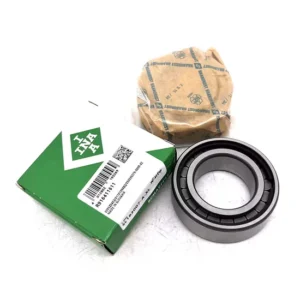
Genuine INA SL183007-A-XL NJ2208 NU2208 Cylindrical Roller Bearing for Auto Parts
INA H7012C-2RZ-P4 B706C T P4S Angular Contact Ball Bearing for Forklift Auto